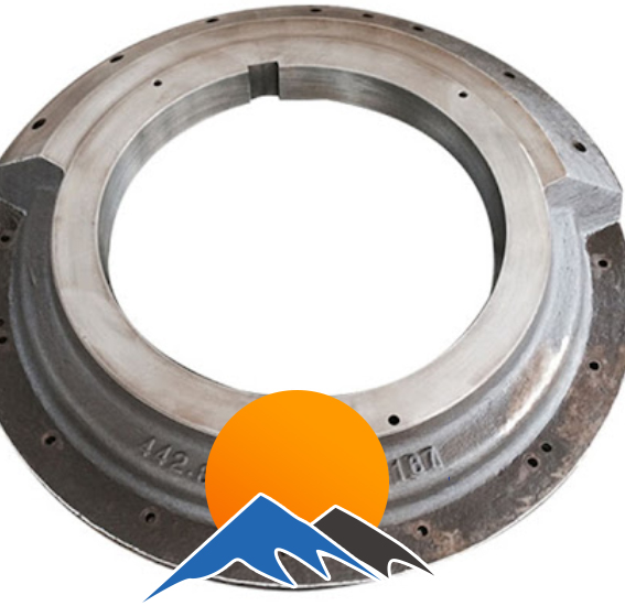
Le palier, élément clé des concasseurs à mâchoires, supporte l'arbre excentrique grâce à des roulements, supportant ainsi les charges radiales et axiales. Fabriqué en QT500-7/HT350/ZG35SiMn, il comprend un corps de palier avec un alésage de précision (tolérance H7), une bride de montage, des rainures d'étanchéité et des nervures radiales.
La fabrication comprend une coulée en fonte ductile (coulée à 1 350–1 420 °C) avec sphéroïdisation, suivie d'un usinage de précision (alésage Ra ≤ 1,6 µm) et d'un traitement de surface. Le contrôle qualité comprend des contrôles de sphéroïdisation (≥ 80 %), un contrôle dimensionnel (coaxialité ≤ 0,05 mm) et des essais de charge (1,5 × charge nominale, déformation ≤ 0,05 mm).
Essentiel pour le fonctionnement stable de l'arbre excentrique, il assure 3 à 5 ans de service avec une lubrification adéquate, préservant ainsi la durée de vie des roulements et l'efficacité du concasseur.
Detailed Introduction to the Bearing Block Component of Jaw Crushers
The bearing block is a core component in jaw crushers that supports the eccentric shaft. Mounted in the bearing block bores of the side plates, it converts the rotational motion of the eccentric shaft into the oscillating motion of the swing jaw via bearings, while withstanding radial and axial loads generated during crushing. Its structural precision and load-bearing capacity directly affect the operational stability of the eccentric shaft, bearing service life, and overall vibration/noise levels of the crusher, making it a critical transmission support component for efficient equipment operation.
I. Composition and Structure of the Bearing Block
Bearing blocks are designed to accommodate different bearing types (mostly spherical roller bearings) and crusher specifications (50–200 kg for small/medium units, over 500 kg for large units). Their main components and structural features are as follows:
Bearing Body The core load-bearing structure, cylindrical or block-shaped, made of high-strength gray cast iron (HT350), ductile iron (QT500-7), or cast steel (ZG35SiMn). Cast iron bodies offer good vibration damping (suitable for small/medium crushers), while cast steel bodies provide higher strength (suitable for large crushers). The body contains a precision bore for bearing installation, with external mounting flanges and reinforcing ribs. The overall structure must resist plastic deformation under 1.5× rated load.
Bearing Bore A precision through-hole at the center of the body for mounting the bearing outer ring, with a tolerance of H7 (interference fit) based on bearing requirements. The inner surface roughness is Ra ≤1.6 μm (to reduce wear on the bearing outer ring). Steps (10–20 mm wide) at both ends of the bore locate the bearing and seal cover, with perpendicularity of the step faces to the bore axis ≤0.02 mm/100 mm to ensure uniform force distribution after bearing installation.
Mounting Flange A flanged structure at one or both ends of the body, 10–20 mm thicker than the body, for bolted connection to the side plates. The flange face features 4–8 circumferential bolt holes (M16–M36) with a positional tolerance of ±0.2 mm. The flatness of the mating surface with the side plate is ≤0.1 mm/100 mm to prevent eccentric loading after installation.
Sealing Structure (Sealing Groove) Sealing grooves (8–15 mm wide, 3–5 mm deep) at both ends of the bearing bore house oil seals or labyrinth seals, preventing lubricant leakage and dust ingress. The coaxiality of the sealing groove with the bearing bore is ≤0.05 mm to avoid seal wear due to eccentricity.
Reinforcement and Auxiliary Structures
Radial Ribs: 15–30 mm thick radial ribs on the body exterior form triangular supports with the mounting flange, enhancing radial load resistance (deflection ≤0.1 mm/m).
Oil Filling Hole: A M10–M16 threaded hole on the body side connects to a grease nipple or lubrication pipe for bearing lubrication. The 3–5 mm diameter channel links to the bearing bore to ensure adequate lubrication.
Locating Boss (Optional): An annular boss (3–5 mm high) on some flange faces mates with a groove in the side plate, limiting positioning deviation to ≤0.05 mm for improved installation accuracy.
II. Casting Process of Bearing Blocks (Ductile Iron QT500-7 Example)
Ductile iron bearing blocks are widely used for their balance of strength and damping. The casting process ensures spheroidization rate and internal quality:
Mold and Sand Preparation
Resin sand molds are used, with wooden or metal patterns based on 3D models. A 1.0%–1.5% shrinkage allowance (ductile iron linear shrinkage) is reserved. The bearing bore is formed with sand cores coated in graphite paint (0.5–1 mm thick) to improve surface precision.
Sand core alignment ensures ≤0.1 mm/m perpendicularity deviation of the bearing bore to prevent eccentricity in castings.
Melting and Spheroidization
Low-sulfur pig iron (S ≤0.03%), scrap steel, and return material are melted in an induction furnace to 1450–1480°C. Composition is adjusted (C 3.6%–3.8%, Si 2.5%–2.8%, Mn ≤0.5%).
Spheroidization: Using the 冲入法,spheroidizing agent (rare earth magnesium alloy, 1.2%–1.5%) and inoculant (75% ferrosilicon, 0.8%–1.0%) are added to the ladle. Post-treatment melt temperature is 1380–1420°C, with a spheroidization rate ≥80% (grade ≥3).
Pouring and Cooling
A bottom-pouring system fills from the body’s bottom center at 1350–1380°C. Pouring time is 3–10 minutes (50–500 kg weight) to ensure smooth filling without slag entrapment.
Castings cool below 300°C in the mold to avoid cracking from rapid cooling.
Heat Treatment
Annealing: Castings are heated to 550–600°C, held for 3–4 hours, then furnace-cooled to 200°C for air cooling to eliminate residual stress (≤80 MPa) and prevent machining deformation. Cast steel components undergo normalizing (850–900°C for 2 hours, air-cooled) for uniform structure.
III. Machining Process of Bearing Blocks
Rough Machining
Using the flange face as a datum, the bearing bore is rough-turned/milled (2–3 mm finish allowance) on a lathe or vertical machining center. The flange face is rough-milled (1–2 mm allowance) to ensure ≤0.3 mm/100 mm perpendicularity between the bore axis and flange face.
Bolt holes and oil filling holes are drilled (1 mm allowance), and sealing grooves are rough-turned (0.5 mm allowance on width/depth).
Aging Treatment
Post-roughing, artificial aging is performed (200–250°C for 4 hours for cast iron; 300–350°C for 6 hours for cast steel) to further relieve machining stress and stabilize dimensions.
Finish Machining
Bearing bore: Finish-bored on a CNC lathe or boring machine with diamond tools (cast iron) or carbide tools (cast steel) to H7 tolerance, Ra ≤1.6 μm, and cylindricity ≤0.005 mm/100 mm.
Flange face: Finish-milled to flatness ≤0.1 mm/100 mm, perpendicularity to the bore axis ≤0.01 mm/100 mm, and Ra ≤3.2 μm.
Sealing grooves and threads: Finish-turned sealing grooves (±0.1 mm tolerance) and tapped oil holes (6H thread) ensure reliable seal and fastener fit.
Surface Treatment
Unmachined surfaces are deburred and painted with anti-rust coating (phosphated for cast iron). Machined surfaces receive anti-rust oil. Bearing bores for large units may be phosphated or chrome-plated (5–10 μm) for wear resistance.
IV. Quality Control Process
Casting Quality
Visual inspection: No cracks, shrinkage, or sand holes. The bearing bore surface must be free of ≥1 mm diameter pores or inclusions.
Internal quality: Ductile iron is inspected for spheroidization rate (≥80%) and graphite morphology (predominantly spherical). Cast steel undergoes ultrasonic testing (UT), with no ≥φ2 mm defects within 20 mm of the bearing bore.
Mechanical properties: Sampled for hardness (QT500-7: 170–230 HBW; ZG35SiMn: 220–260 HBW) and tensile strength (QT500-7: ≥500 MPa).
Dimensional Accuracy
Coordinate measuring machines verify bearing bore diameter (H7), cylindricity, perpendicularity to the flange, and bolt hole positions, with key deviations ≤50% of design tolerances.
A dial gauge checks flange flatness (≤0.1 mm/100 mm) and sealing groove coaxiality (≤0.05 mm).
Assembly Testing
Bearing fit: A standard bearing outer ring is pressed into the bore to verify interference (0.01–0.03 mm), ensuring no looseness or excessive tightness.
Seal testing: Seals are installed for a 0.3 MPa pressure test (30 minutes) with no lubricant leakage.
Load Testing
Static loading at 1.5× rated radial load for 1 hour shows deformation ≤0.05 mm with no residual deformation post-unloading.
With a 3–5 year service life (depending on lubrication and operating conditions), bearing blocks rely on strict process control for performance. Routine maintenance includes checking seals and bolt tightness to prevent premature failure from eccentric loading or poor lubrication